|
Radschool Association Magazine - Vol 21 Page 12 |
|
|
Ken Corkhill sent us this article. Ken was in the RAAF from 1st October 1951 until 30th September 1973. He Graduated on No 5 Radio Technician – Ground course at Ballarat in 1954 and was discharged with the rank of Warrant Officer. He is now retired but voluntary working as Vice President of the Association of Residents of Queensland Retirement Villages.
Evolution.
RAAF Standards Laboratory to PMEL to Base Calibration Centre.
The Panclimatic Section began its life as part of the Aircraft Research and Development Unit (ARDU) at Laverton sometime prior to 1954. In 1954 the Section was under the command of Wng Cdr Clem Blakely (later replaced by Wng Cdr “Bon” Hall if I remember correctly) supported by Sqn Ldr Tim Tyler and assisted by the following civilians: Senior Scientific Officer: StJohn Thorne (imported from England and his name was pronounced Sinjohn), Scientific Officer: Bill Rice and Technical Officer: Kevin Kennedy. The Warrant Officer in charge of the Technicians was Stan Wilson. Some of the technicians include Graham “Gusty” Gale, Keith Aiton, Mark Webster, Ted Plant and Eric Semmler.
Part of this Section was a laboratory that maintained the electronic test equipment used for testing proposed new electronic equipment and components for the RAAF. These new items were tested to ensure they would work under the most arduous conditions. This included extreme heat and humidity plus extreme cold. Not only was the equipment itself tested but all their electronic components as well (you know those funny old things called Resistors, Coils, Condensers and Valves) and this included proposed spare parts. The Section was also directed to develop improvements/modifications to existing electronic equipment to provide better service to the users and correct any known problems.
The modified equipment was required to pass all the stringent tests of new equipment. Not all designs were usable as we found out when someone suggested changing the twin triode valve in the RF section of the 5043 (Below - click for bigger view) with a pentode to obtain better reception over longer distances. While reception 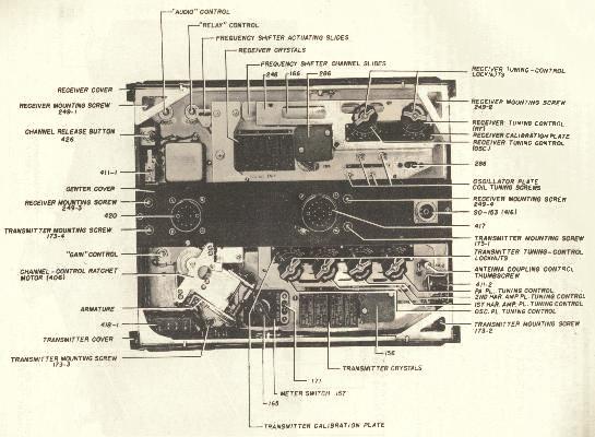 was improved, testing while installed on aircraft it was too sensitive and the vibrations caused it to oscillate uncontrollably.
In order to ensure the accuracy of the tests the Standards Laboratory was set up as part of this scheme to re-calibrate the electronic measuring equipment used in the Panclimatic testing process as well as checking electronic test equipment for the ARDU Aircraft Maintenance Section, Base Radio and No. 1 Aircraft Depot. In those days Signal Generators used for maintaining equipment such as AR7 Receivers, AT17 VHF Transmitters, AT26 HF Transmitters and 5043 VHF Transmitter/Receivers could be checked against an old Beat Frequency Oscillator SCR211 and this was only accurate to about 1 in 104. However, advancing technology made this unacceptable and the Standards Laboratory was set out up rectify this. Signal Generators could then be calibrated against a General Radio (GR) Time Clock which was accurate to just better than 2 in 106 or about 1 second per day. To ensure this accuracy, the Time Clock was checked daily against WWV or WWVH American Standard Time using an old AR7 Receiver. The check was done by listening to the Clock Ticks on the radio until the 59th second which was omitted then visually noting the clock second hand position on the next click. This indicated how many seconds GR Time Clock had lost or gained. After a few years we gained a new Tektronix 545 Dual Beam Oscilloscope which then enabled us to display clock pulses from both the radio and the GR Times Standard. This significantly improved our ability to monitor the time difference over a period.
The capacitance, inductance, voltage and resistance calibration equipment was regularly recalibrated at Defence Standards Laboratory (DSL), Maribyrnong, Victoria. This equipment was then used to check items like the old AVO multimeters in general use at that time. I was also fortunate enough to be nominated as the liaison person for this task and managed to learn a lot from the DSL Engineers regarding both time and components standards during their visits to the Defence Standards Lab.
 A screened room was constructed by the Technicians along with all the mains filtering equipment to avoid any outside interference. The whole room was made from a wooden frame with copper mesh both on the inside and outside of the frame with each layer soldered along the seams. The Mains Filter was a copper box containing condensers and home made coils to remove any spikes from the mains supply. This room was used for the more delicate testing of some specialised electronic equipment in an interference free zone. The quality of the electronic test equipment was gradually improved with the introduction of more modern equipment such as the Hewlett Packard (HP) 524B Electronic Counter (left) which could measure accurately to 1 in 105. This new fangled machine had a display that gave you the frequency down to the last cycle. It was also our first experience with any sort of computing equipment it used to generate the digital display (light emitting diodes or LEDs) and analogue displays (as shown below). More advanced versions of this were later used throughout the RAAF in the form of HP 524C/524CR which had Digital Displays tube displays then later again by the transistorised HP 5245L. Some small improvements were also made in the resistance and capacitance testing equipment during this period.
Some of the new equipment tested during this time included the AN/CPN 4 QUAD Radar and AN/URN3 TACAN systems. Because of the size of these systems, climatic testing was restricted to heating, humidity and cooling testing of the modules. There were also increases in the transmission frequencies from VHF to UHF generating a need for new test equipment and improved accuracy in our measurements. Often these projects required specialised equipment to be manufactured by the Technicians to cater for specific test requirements. This included special small ovens to heat oscillator crystals to their normal operating temperature to ensure their frequency stability plus electronic temperature controllers to maintain the correct temperatures and power. It was during this period that Kevin Kennedy received a small package for evaluation. When first opened it looked like a bunch of resistors until you realised they had three legs and someone had written inside the packages “Transistors” - whatever that meant. They were supposed to take over from valves but how could something that small take over from a 6J6 or 6963 dual triode valves let alone a 6L6, 807 or 3J160E? We tested them and they seemed to do everything they were supposed to but we were never sure that something that small would work in the real world. Little could we visualise at that time they would eventually shrink again and several thousand of them would become enclosed in one “microchip”.
Another example of our tasks (with a humorous twist) was working with Bill Rice on coded teletype transmission security. This involved upgrading our security clearances to the absolute top level in case we became privy to messages for the Air Marshall. When it came time to depart, we loaded our test receivers on a RAAF DC3, signed out our parachutes, got on board and were duly flown to Canberra. Here we spent the next few days wandering around RAAF Headquarters, the Communications Centre and the surrounding PMG phone pits (looking like PMG Technicians) checking for the presence of any signals related to the secure teletype systems. When we arrived at the Airport to go home, we watched our transport, the RAAF DC3, come in to land with obvious engine problems and it was duly grounded. The RTO immediately arranged for us to go home on TAA but they could not take our parachutes as luggage in the hold. You can imagine the worried looks on the other passengers’ faces when two people got on the plane carrying parachutes
Plans were now in progress to further improve
the equipment and the need for extra space was becoming more apparent. A
proposal to move Panclimatic Section to Point Cook and the setting up
of a completely new facility was added in to the plans. The project became
loosely known as “9694” which was the overseas purchase order number. An area adjacent
to the Gymnasium down near the Point Cook pier was
to become our new home and all the insides of the old building were to be
replaced by specially designed rooms. These were consisting of a General
Workshop, Standards Laboratory, Vibration
(the HP 5245L below) Room,
The new Rohde &
Schwartz CA78 Time and Frequency
Standard was eventually installed along with a Rohde & Schwartz XZF
As the Frequency Standard had to be operational
24 hours a day to maintain its accuracy, a standby power 24 volt DC supply
consisting of 4 huge 6 volt batteries was installed. These had to be
checked regularly and continuously recharged adding to the list of our
daily chores. It was during one of these weekly tests that Sgt Eddie Witts
suffered eye injury from acid when refilling the batteries and required a
rapid ride to the Base Hospital. Fortunately he suffered no permanent
damage. New HF, VHF and UHF aerials were required and we had to design
an aerial platform to be erected on the rooftop to allow the Laboratory
Technicians to install the required aerials. It consisted of a square
safety platform with the VHF and UHF aerials attached to the posts on the
corners and a stairway from the roof’s edge up to the platform. The HF
aerials were mounted between poles at the ends of the roof. These aerials
were also wired into the patch panel. Instead of using visual time
checks we invented a way to use the 524B counter to measure the precise
time differences between WWV time and the CA78 time. Having calibrated the
CA78 we could then check the XZF against the CA78 to ensure its accuracy
as well. The accuracy of the XZF and 524B were also improved as we could
use an external frequency of 100 kilocycles obtained directly from the
Time Standard instead of the built in crystal oscillators.
We could monitor the entire local (and some distant) RAAF HF, VHF and UHF transmitters and check their frequencies. The RAAF School of Languages located in an adjacent building took advantage of this capability. The instructors and students used to come in and listen to Indonesian broadcast stations and practiced translating what they heard. Our testing now included checking with the PMG’s “Talking Clock” each week and advising them of its accuracy. This was done over the phone line which in those days went thru the Base Switchboard as there was no direct dialling. The time variations of the pulses from the PMG’s base system and the CA78 were plotted over a period of time and used to calculate the drift in the PMG system. All of the testing carried out had to be documented both as to the procedures to be used and the certifying by the tester that they had been carried out correctly. Most of this paperwork fell to ‘yours truly’.
Some time and frequency liaison was also done with the National Standards Laboratory at Mt Stromlo in Canberra but, as we were both on the same standard of accuracy further regular checking with them was not pursued at that time. One of the new items was our first experience of a calculator. It was extremely large compared to today’s instruments but was far better than something like a slide rule, Abacus or “fingers and toes”. The user only had to put the numbers into the Marchant Calculator to get the answers. Of course there was the problem that you still had to pull the handle and wait for the wheels to stop turning but at least it gave the correct answer for multiplication, division, addition and subtraction. We thought it was marvellous at the time.
Improvements were also made with the resistance, current and capacitance measuring equipment along with much better vibration testing devices. Where we were restricted to 1% previously this had become 0.2% or better. When designing the benches we had to take cognisance of the size and weight of the Resistance/Voltage/Current test instrument and make provision for extra legs under the bench on which it was to be located. It became a standing joke among the other Radio Technicians in other units that we were supposed to have thought we were able to measure the capacitance between “two cat’s hairs 50 feet apart". The old Humidity Chamber and small Refrigeration Chamber were moved down from Laverton and a new large Refrigeration Chamber installed along with several smaller humidity ovens. The large Humidity Chamber required considerable updating as it was constructed from an old packing case which had been insulated and radiator elements and water heaters installed in a tunnel down the back of the case. The tunnel casing was reworked and new heating elements installed along with a Laboratory built electronic temperature and humidity controllers.
This new and updated equipment
gave us the ability to test equipment and components in conditions ranging
from -55C up to 50C at 95% relative humidity. This included trying to grow
fungus on equipment and components that were scheduled for operation in
tropical areas. New components would be placed in small
(HP 608D VHF Signal Generator)
ovens and sprayed with a mixture of
bacteria and left to cook at 45C and 95%
By now it was early 1960’s and there were stories that the American Air Force had set up similar Standards Laboratories on all their bases and had called them Precision Measuring Electronic Laboratories (PMEL’s). HQ Support Command sought the assistance of the Standards Laboratory in deciding the makes and models of the equipment to be provided to set up these new PMELs on some of our own bases. In 1963 the RAAF decided I would be better employed looking after the support of all RAAF electronic test equipment and duly moved me into Spares Assessing Section in HQSUPCOM. Here we started rationalising all the electronic test equipment and their spare parts by introducing a system of preferred items of test equipment for a given task. The idea being to reduce the maintenance costs by reducing the variety of similar equipments in use for the same purpose. This also included replacing as much aged electronic test equipment as possible as there was still considerable amount very old equipment in use at that time. There was also the clearing out of the unwanted spare parts for this equipment still being held in our stores depots.
It was also around this time that Hewlett Packard was experimenting with the 5060A “Travelling Clock” which was being regularly flown between Palo Alto and Switzerland to ensure its accuracy. This new device was the Caesium Beam Standard with an accuracy of 1 second in 3,000 years (2 in 1011). This was seen as a stupendous step forward and, when they became available after 1964, we recommended that some of these be purchased for selected PMELs such as Richmond, Williamtown and Townsville Bases. Later, when the F111’s were purchased, Amberley was also included. As part of the standardisation process for new RAAF purchases, even as a Ground Radio Technician, I was seconded to the F111 project at Carswell AFB in Forth Worth (“Cow Town”) for six months. I also liaised with and visited the Orion project in Hollywood CA. Other visits were made to Hewlett Packard in Palo Alto CA and other companies in Rochester NY and Great Neck NY. The purpose of this was to standardise, as far as possible, the electronic test equipment used on both the F111 and Orion Projects looking at both the operational aspects together with any ongoing calibration and maintenance issues.
The PMELs have now been renamed “Base Calibration Centres” and while their functions are similar to the original Standards Laboratory, the level of accuracy is rather incomprehensible for someone in the older age group. Frequency testing is carried out against the International Time Standard in Switzerland and is to the order of 1 part in 1012 or better. While previously there had been the movement from the old VHF transmissions into UHF this has now gone into the Gigahertz range and communications are no longer made using HF and/or VHF transmissions but satellite communications and equipment has been reduced in size so much that it is almost unrecognisable to someone of my era.
|
|
|
In English pubs, ale is ordered by pints and quarts. So in olde England, when customers got unruly, the bartender would yell at them to mind their own pints and quarts and settle down. It's where we get the phrase "mind your P's and Q's" |
Many years ago in England, pub frequenters had a whistle baked into the rim or handle of their ceramic cups. When they needed a refill, they used the whistle to get some service. "Wet your whistle," is the phrase inspired by this practice |
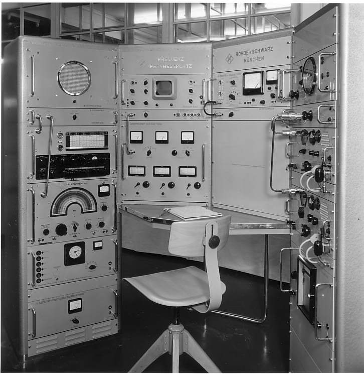
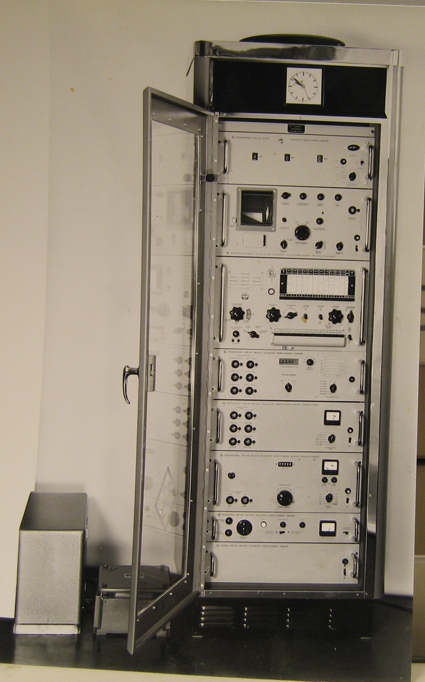 Frequency Measuring Station. The CA78 (left) was in a single equipment rack
cabinet and the XZF (below) was in the form of 4 cabinet racks in a semi circle as
a work station. The XZF contained several radio receivers and a special
Oscilloscope to compare the frequency differences when testing. The
frequency of the incoming signal could be measured accurately knowing that
when the rotating circle on the Oscilloscope was
stable then the incoming frequency was exactly 1,000 cycles above the
Standard Frequency set. The improvement in our measuring capabilities
was incredible. The Time Standard became 1 or 2 parts in 108 (one second
in 1.5 years) while the Frequency Measuring Station was around 1 in 106 (one
second in 5.4 days). Our reception frequencies were now between 50
kilocycles and about 300 megacycles and so we could monitor WWV and WWVH
as well as GBR which was Greenwich Time. Cabling from these instruments
was via a patch panel and routed around the Standards Laboratory and to
all the other areas in the Panclimatic Section. This enabled accurate
frequency checking to be carried out in other areas without the need to
move equipment around.
Frequency Measuring Station. The CA78 (left) was in a single equipment rack
cabinet and the XZF (below) was in the form of 4 cabinet racks in a semi circle as
a work station. The XZF contained several radio receivers and a special
Oscilloscope to compare the frequency differences when testing. The
frequency of the incoming signal could be measured accurately knowing that
when the rotating circle on the Oscilloscope was
stable then the incoming frequency was exactly 1,000 cycles above the
Standard Frequency set. The improvement in our measuring capabilities
was incredible. The Time Standard became 1 or 2 parts in 108 (one second
in 1.5 years) while the Frequency Measuring Station was around 1 in 106 (one
second in 5.4 days). Our reception frequencies were now between 50
kilocycles and about 300 megacycles and so we could monitor WWV and WWVH
as well as GBR which was Greenwich Time. Cabling from these instruments
was via a patch panel and routed around the Standards Laboratory and to
all the other areas in the Panclimatic Section. This enabled accurate
frequency checking to be carried out in other areas without the need to
move equipment around.